
EXECUTIVE SUMMARY
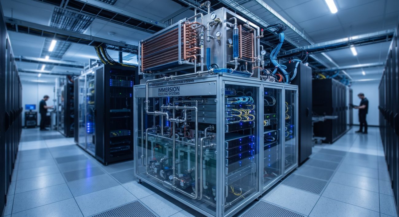
The Two-Phase Immersion Cooling Vapor Condenser Heat Exchanger Geometry defines the critical thermal boundary between the sealed immersion tank and the facility cooling loop. This OEM whitepaper specifies the condenser’s geometric architecture, fin-tube configuration, and material metallurgy required to achieve stable dropwise condensation of dielectric vapor at high heat flux. The geometry is optimized for low-pressure drop, uniform vapor distribution, and maximum latent heat rejection per unit volume, enabling single-phase facility water or high-temperature chilled water operation. This document is intended for datacenter architects, thermal engineers, and system integrators deploying high-density compute in two-phase immersion environments.

ARCHITECTURE & CHASSIS DESIGN
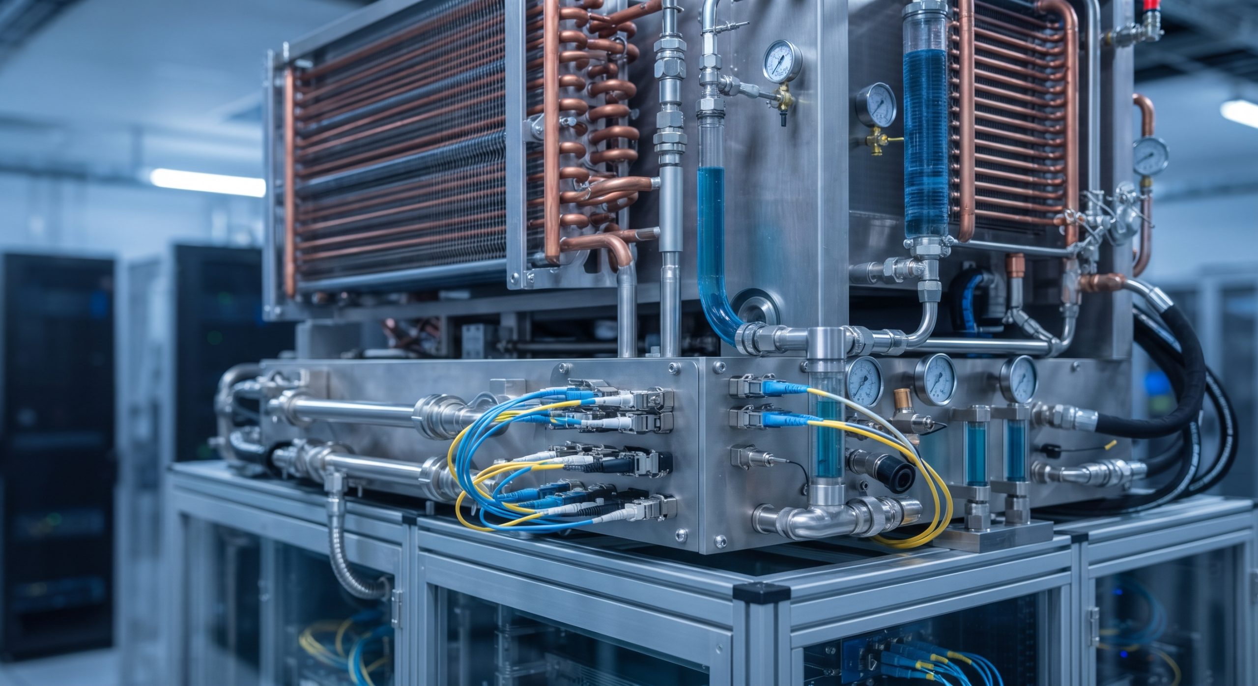
The vapor condenser heat exchanger is configured as a vertical coil bank positioned in the ullage space above the immersion bath. The geometry utilizes a staggered array of horizontal finned tubes with a continuous serpentine circuit, ensuring counter-flow heat exchange between ascending dielectric vapor and descending facility coolant. Tube pitch, fin density, and coil face area are balanced to maintain vapor velocity below the entrainment threshold while maximizing condensate film drainage. The condenser housing incorporates a sloped condensate trough and a demister mesh to prevent droplet carryover into the vapor zone. All wetted surfaces are compatible with dielectric fluids such as Novec and Opteon, with stainless steel 316L headers and aluminum fins treated for corrosion resistance.
HARDWARE FEATURES
– Geometric tube geometry: 9.52 mm OD finned tubes with 2.1 mm fin pitch and 0.15 mm fin thickness for high surface area density.
– Coil face area: 0.6 m² to 2.4 m² depending on heat rejection class, scalable via modular coil cassettes.
– Vapor distribution manifold: perforated header with CFD-optimized orifice pattern for uniform vapor approach velocity.
– Condensate management: sloped trough with 5° drainage angle and return line sized for full reflux flow.
– Material compatibility: SS316L tube headers, aluminum fins with hydrophobic coating, and EPDM gaskets rated for dielectric service.
– Serviceability: removable coil cassettes with quick-disconnect coolant fittings for in-situ maintenance.
COMPLIANCE & STANDARDS
The condenser geometry is designed to meet ASHRAE 90.4 energy efficiency requirements for datacom cooling, and is compliant with IEC 60335-2-40 for electrical safety of heat exchangers. Pressure vessel headers conform to ASME B31.3 where applicable. RoHS and REACH compliance is maintained for all wetted materials. The design supports OCP Immersion Cooling requirements and is compatible with Open19 and OCP Accepted rack architectures.
TECHNICAL SPECIFICATIONS
The following parameter registry defines the geometric and thermal performance envelope of the vapor condenser heat exchanger. Values are nominal at rated conditions with facility water inlet temperature of 32°C and dielectric vapor temperature of 50°C.
| Parameter | Specification |
|---|---|
| Form Factor | Vertical coil bank, modular cassette architecture |
| Heat Rejection Capacity | 100 kW / 250 kW / 500 kW nominal classes |
| Tube Geometry | 9.52 mm OD finned tubes, 2.1 mm fin pitch |
| Coil Face Area | 1.0 m² to 2.4 m² depending on class |
| Coolant Connection | 3/4-inch to 1.5-inch NPT/BSPP |
| Wetted Materials | SS316L headers, aluminum fins, EPDM gaskets |
| Design Pressure | Facility loop: 10 bar; vapor side: 1.5 bar |
| Operating Temperature | Facility water: 15°C to 45°C; vapor: 40°C to 65°C |
| Pressure Drop | ≤ 30 kPa on facility coolant side at rated flow |
| Condensate Drain | 5° sloped trough with 1-inch return connection |
| Compliance | ASHRAE 90.4, IEC 60335-2-40, RoHS, REACH |
| Serviceability | Removable cassettes with quick-disconnect fittings |
ORDERING OPTIONS
– VC-100: 100 kW heat rejection class, single coil cassette, 1.0 m² face area, 3/4-inch coolant connections.
– VC-250: 250 kW heat rejection class, dual coil cassettes, 1.6 m² face area, 1-inch coolant connections.
– VC-500: 500 kW heat rejection class, four coil cassettes, 2.4 m² face area, 1.5-inch coolant connections.
– Accessory kits: condensate return line kit, demister replacement mesh, and hydrophobic coating refresh service.
📥 Download Technical Specification
Click the button below to view or download the full official PDF datasheet.
Leave a comment