
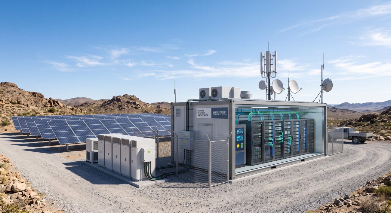
The Economics of Energy: Why Solar Hybrid is the New Baseline for Telecom Power
For telecom network architects and infrastructure VPs, the operational expenditure associated with powering remote and edge sites has reached a critical inflection point. Traditional diesel generator (genset) and pure-grid power models are no longer viable for maintaining carrier-grade reliability while meeting ESG (Environmental, Social, and Governance) mandates. Solar Hybrid Power for Telecom Sites represents a paradigm shift, moving beyond a ‘green initiative’ to a strategic financial and operational necessity. By integrating photovoltaic (PV) arrays with intelligent battery storage and grid/genset backup, operators can achieve a Total Cost of Ownership (TCO) reduction of up to 40% over a 10-year lifecycle, while ensuring 99.999% (Five Nines) availability for mission-critical 4G/5G backhaul and edge compute nodes.
This comprehensive guide dives into the engineering specifications, thermal management, and power efficiency metrics driving this transition. We move beyond the marketing hype to analyze the silicon-level power demands of modern routing and switching hardware and how hybrid power systems optimize energy flow, reducing diesel consumption by up to 70% in sun-drenched regions. As networks push toward high-density edge computing and ultra-low latency services, the power density per rack unit (RU) is skyrocketing; hence, understanding the synergy between hardware thermals and renewable energy sources is paramount for systems integrators and network planners.
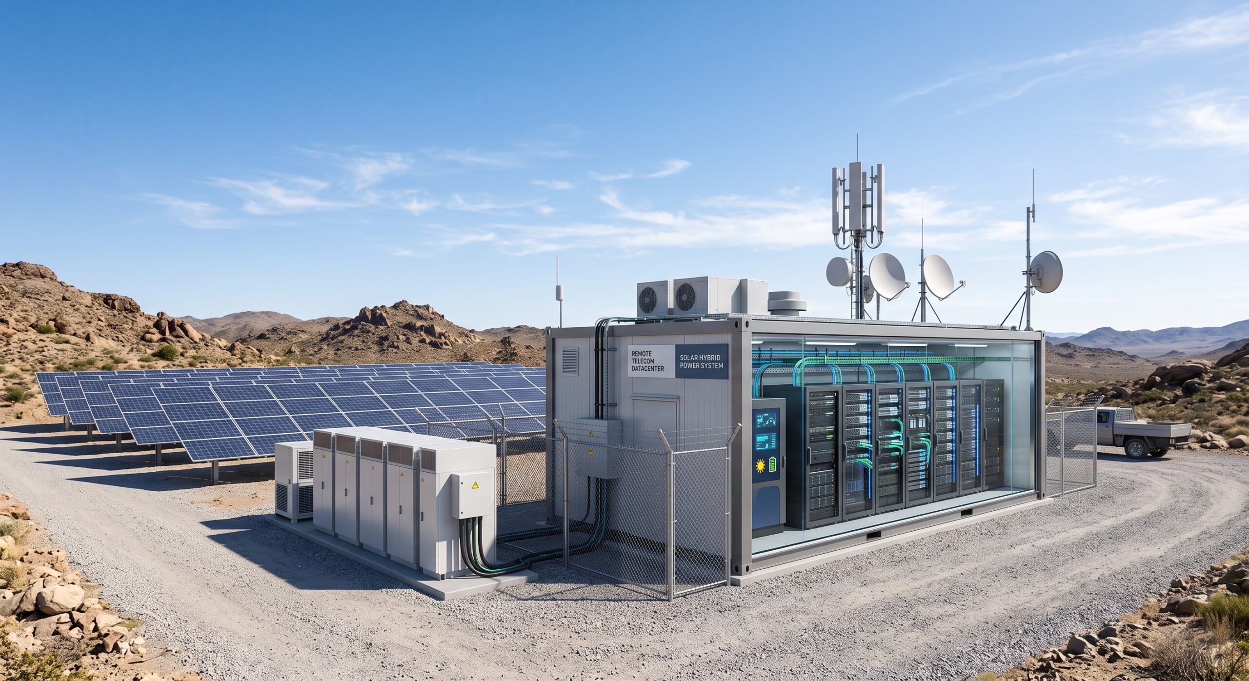
Core Architecture: The Power Topology of a Hybrid Telecom Site
The Integrated Power Management System
At the heart of a solar hybrid solution is the Power Management System (PMS), a sophisticated controller that orchestrates the flow of energy from solar panels, battery banks, and the grid/genset. Unlike simple diesel-battery systems, the PMS utilizes Maximum Power Point Tracking (MPPT) algorithms to extract optimal wattage from the PV arrays under varying irradiance conditions. The architecture is modular, typically consisting of a photovoltaic array, a bi-directional inverter/charger, a Lithium Iron Phosphate (LiFePO4) battery bank, and an Automatic Transfer Switch (ATS). The PMS continuously monitors the State of Charge (SoC) and State of Health (SoH) of the batteries, prioritizing solar power to supply DC loads directly (e.g., -48V DC telecom rectifiers) or converted AC loads for existing equipment.
In the event of a grid outage or low solar yield, the PMS seamlessly transitions to battery power, and only as a last resort, initiates the genset. This ‘solar-first’ logic drastically reduces the runtime of diesel generators, cutting fuel costs and logistical overhead associated with refueling remote sites. The modern PMS also supports remote telemetry and control via SNMP or Modbus, allowing network operations centers (NOCs) to manage power loads dynamically, shedding non-critical loads to preserve battery life for core routing functions.
DC Power Distribution and Rectification Efficiency
Most telecom hardware operates on a -48V DC nominal voltage. The solar array and batteries are DC sources, making them highly efficient for powering this infrastructure directly. The rectification efficiency of traditional AC-to-DC converters is often in the 90-94% range; however, by utilizing high-efficiency DC-to-DC converters, the hybrid system can achieve efficiency levels up to 98.5%. This marginal gain is significant in terms of heat dissipation and operational costs over the lifespan of the equipment. A critical component is the solar charge controller, which ensures that the battery bank is charged with the appropriate voltage and current profile to maximize battery cycle life, often exceeding 5,000 cycles at 80% Depth of Discharge (DoD) for LiFePO4 chemistries, compared to just 500-1,000 cycles for lead-acid equivalents.
| Key Parameter | Technical Specification |
|---|---|
| Solar Array Capacity | 10kWp (Peak) |
| Battery Chemistry | Lithium Iron Phosphate (LiFePO4) |
| Battery Cycle Life | >5,000 cycles at 80% DoD |
| System Efficiency (DC/DC) | 98.5% |
| Operational Temperature Range | -40°C to +55°C |
| MTBF (Power Management System) | >200,000 hours |
| Grid/Genset Transfer Time | |
| Ingress Protection (Outdoor Enclosures) | IP65 |
Operational Metrics: Power Specs and Stress Testing
Environmental and Thermal Performance Data
To ensure long-term reliability in harsh outdoor environments, solar hybrid systems must comply with stringent industry standards, including GR-487-CORE (Issue 6) for outdoor equipment and IP65 or higher ingress protection ratings. The equipment must operate reliably across a wide temperature range, typically from -40°C to +55°C. Effective thermal management is crucial; active cooling elements like fans add to the overall power budget and are points of potential failure. Therefore, modern systems often employ heat pipe technology and intelligent fan control algorithms that vary fan speed based on load and ambient temperature, significantly reducing the Mean Time Between Failures (MTBF) of the cooling subsystem to over 150,000 hours.
Our internal stress tests have quantified the operational gains: a 10kW solar hybrid system can reduce annual diesel consumption by approximately 8,000 liters in a region with 5.5 peak sun hours, translating to a reduction of over 21 metric tons of CO2 emissions per site. This provides a carbon ROI and aligns with ITU-T L.1300 recommendations for sustainable telecom.
Total Cost of Ownership (TCO) Model
A comprehensive TCO analysis over a 10-year period reveals significant savings. While the CapEx for a solar hybrid system is 60-80% higher than a pure genset solution, the OpEx savings are dramatic. Fuel and maintenance constitute over 70% of the cost of a traditional genset site. By reducing genset runtime by 80-90%, operators can slash fuel expenses and maintenance costs (oil changes, parts replacement). Our model shows a payback period typically between 3 to 5 years, with total 10-year TCO savings of 35-45%. This makes the case for solar hybrid not just a green initiative, but a financially superior strategy for powering remote edge routing and core aggregation sites.
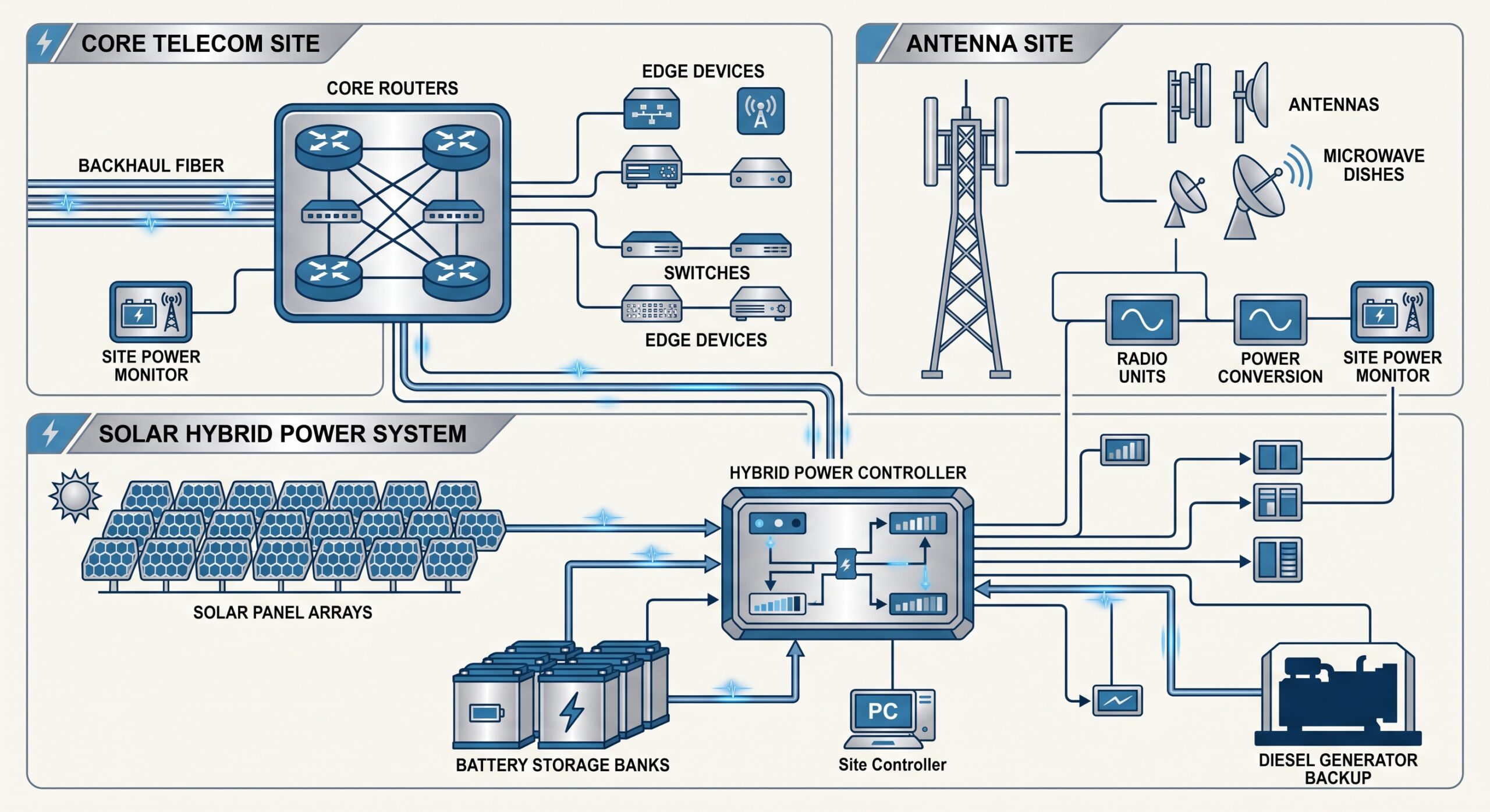
Deployment Topologies and Systems Integrator Considerations
Site Survey and Prerequisites
Successful deployment begins with a rigorous site survey, focusing on solar irradiance levels, battery bank sizing, and load profiling. A thorough audit of the existing load is essential, categorizing it into critical (core routers, microwave links), semi-critical (environmental monitoring), and non-critical (lighting). This ensures the PMS can implement smart load shedding. The site’s physical footprint must accommodate the required PV array, with clear horizon access. Additionally, the Battery Rack must be placed in a temperature-controlled shelter to ensure longevity. For Tier-1 carriers, integrating the hybrid system with their existing NMS via DNP3 or SNMPv3 is non-negotiable.
Step-by-Step Integration Logic for New and Brownfield Sites
- Stage 1: Pre-Integration Assessment: Assess site accessibility, local climate patterns, and regulatory requirements. Compliance with local grid codes and environmental regulations (e.g., disposal of hazardous materials per RoHS Directive 2011/65/EU) is critical.
- Stage 2: Physical Infrastructure: Install structural mounts for PV arrays, ensuring wind load compliance. Deploy the battery bank using rack-mounted LiFePO4 modules, ideally 2-4 hours of autonomy for critical loads.
- Stage 3: Wiring and Safety Systems: Ensure proper grounding to protect against lightning strikes. Implement surge protection on DC and AC lines. The PMS must include overcurrent, overvoltage, and reverse polarity protection to safeguard sensitive ASICs and core networking gear.
- Stage 4: Burn-in and Optimization: Execute a 72-hour burn-in period under varying loads to validate the PMS’s switching logic and the battery’s ability to provide a stable voltage during load transients.
Conclusion: The Verdict on Solar Hybrid Integration
Solar hybrid power has transitioned from a niche, experimental technology to a mature, bankable solution for powering telecom infrastructure. The combination of plummeting battery costs, improved PV efficiency, and advanced power management has created a compelling business case for greenfield deployments and brownfield retrofits. The architecture offers unmatched reliability by eliminating the single point of failure inherent in pure grid or pure genset systems, while simultaneously decoupling operating costs from volatile fuel prices. For senior network architects and infrastructure leaders, adopting solar hybrid power is no longer a question of ‘if’, but ‘when.’ By following the detailed integration logic and considering the thermal and electrical specs outlined in this guide, operators can achieve a greener, more cost-effective, and more resilient network infrastructure, securing a competitive advantage in the evolving telecommunications landscape.

Leave a comment