- Description
- Reviews (0)
Description
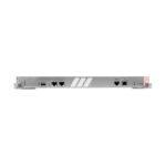
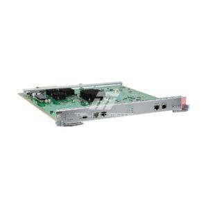
LST7MPUE0000 Overview
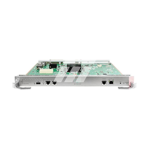
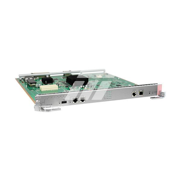
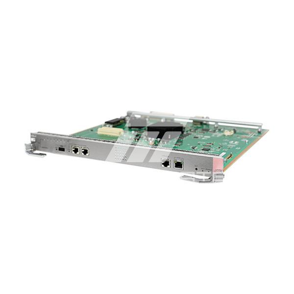
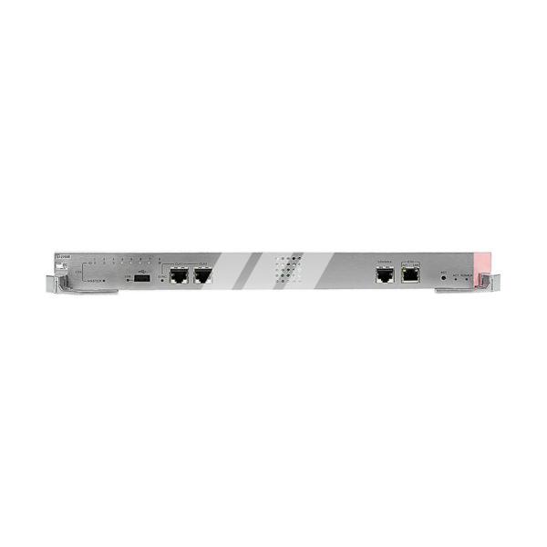
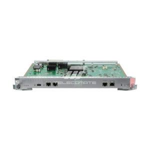
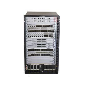
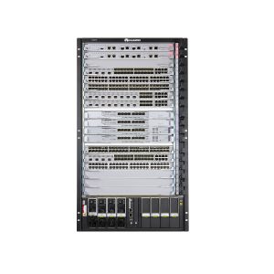
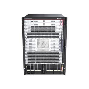
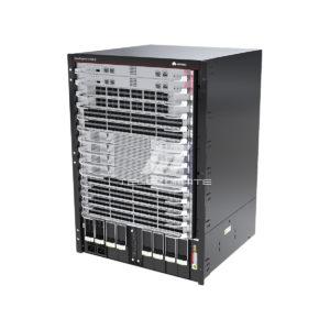
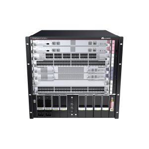
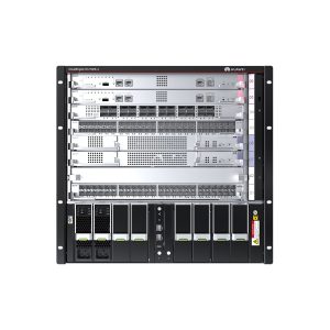
The LST7MPUE0000 is the main control unit for the S12700E-4, S12700E-8, and S12700E-12. It provides the control plane and management plane for the entire system and reserves a slot for clock daughter card.
The LST7MPUE0000 can be installed in:
- Slots 05 and 06 in an S12700E-4 chassis.
- Slots 09 and 10 in an S12700E-8 chassis.
- Slots 13 and 14 in an S12700E-12 chassis.
Switch chassis and software versions matching the card
|
Card Name |
S12700E-4 and S12700E-8 Chassis |
S12700E-12 Chassis |
|---|---|---|
|
LST7MPUE0000 |
Supported in V200R019C00 and later versions |
Supported in V200R019C00 and later versions |
Functions
The LST7MPUE0000 provides the control plane and management plane for the entire system.
- The control plane provides functions such as protocol processing, service processing, route calculation, forwarding control, service scheduling, traffic statistics collection, and system security.
- The management plane is responsible for system status monitoring, environment monitoring, log and alarm processing, system software loading, and system upgrades.
The LST7MPUE0000 consists of the following functional modules:
- Control module: functions as the control and management plane for the LST7MPUE0000 and the entire system, implementing protocol processing, route calculation, forwarding control, system management, and system security.
- Local clock module: provides the working clock for the chips of the control module, and device management and monitoring module on the LST7MPUE0000.
- Device management and monitoring module: provides functions of a controller area network (CAN) bus module to monitor the LST7MPUE0000 and manage the CAN bus modules of LPUs.
- Power supply module: provides power supply for the LST7MPUE0000.
- Value-added service module: provides enhanced services such as operation, administration and maintenance (OAM) and bidirectional forwarding detection (BFD).
Ports on the LST7MPUE0000 panel

| 1 | One USB port. A USB flash drive can be inserted into this port to load the system software to the switch during device deployment. |
| 2 | Two BITS ports. The CLK1 and CLK2 ports on the MPU map the BITS0 and BITS1 ports on the clock daughter card. BITS devices or other products can connect to BITS ports to synchronize the time and clock.
NOTE: LST7MPUE0000 does not support stratum-3 clock, synchronous Ethernet, and IEEE 1588v2 functions. |
| 3 | One console port, used for onsite configuration of the switch. |
| 4 | One ETH management port (10M/100M BASE-TX auto-sensing). It can connect to a network port of a configuration terminal or network management workstation to set up a local or remote configuration environment. |


Reviews
There are no reviews yet.